Wiring vs. Sensor: Why Your Diagnostic Code Might Be Pointing at the Wrong Suspect
Your check engine light comes on. You pull the code — let's say a P0118, coolant temperature sensor reading high. Your mechanic quotes you a coolant temp sensor, maybe $40 for the part plus an hour of labor. Sounds reasonable. You approve the repair. Two weeks later, same code. Different shop, same diagnosis. Another sensor.
Here's the thing nobody told you: OBD-II codes describe a symptom inside the data, not a verdict on which part failed. A P0118 means the ECU received a signal outside its expected range — it does not mean the sensor itself is broken. That out-of-range signal could be coming from a corroded connector, a chafed wire shorting against the firewall, a broken ground, or moisture in a harness. The sensor might be perfectly fine, just starved of clean voltage or a solid reference signal.
This distinction matters a lot when you're trying to avoid throwing money at the wrong part.
Why Wiring Gets Overlooked So Often
Sensors are easy to blame. They're cheap, they're accessible, and replacing one feels like progress. Wiring problems, on the other hand, are slow to find and easy to miss without the right tools or patience. A hairline crack in a wire might only break contact when the engine is hot or when the car hits a bump at highway speed — conditions that are hard to replicate on a lift.
There's also the shop economics angle. A sensor swap is billable in under an hour. Chasing a wiring gremlin through a harness can eat an entire afternoon with no guarantee of a clean answer. Some shops skip the circuit verification step entirely and go straight to the most common fix. That's not always negligence — sometimes it's a calculated bet that pays off. But when it doesn't, you're the one funding the next round of parts.
The First Thing to Check: Connector Condition
Before you even think about swapping a sensor, physically inspect the connector that plugs into it. You're looking for:
- Green or white corrosion on the terminals — this increases resistance and distorts the signal the sensor sends
- Pushed-back or bent pins that aren't making full contact
- Melted plastic or heat damage near the connector body, which suggests a nearby exhaust or electrical issue
- Moisture or oil contamination inside the connector housing
If any of those are present, you've got a legitimate lead. A corroded connector can make a perfectly good sensor look completely dead to the ECU. Cleaning the terminals with electrical contact cleaner and a small brush sometimes resolves a code without replacing anything.
Breaking Out the Multimeter
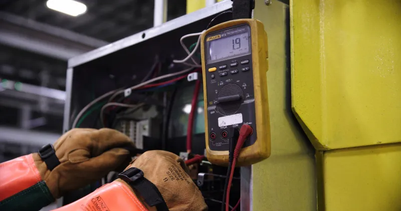
This is where DIYers can really get ahead of the problem. A basic multimeter — even a $20 one from an auto parts store — lets you test the circuit feeding your sensor directly. Here's the general approach:
Check reference voltage. Most sensors operate on a 5-volt reference signal supplied by the ECU. With the ignition on and engine off, backprobe the reference wire at the sensor connector (your vehicle's wiring diagram will tell you which pin). You should see somewhere in the 4.8–5.2V range. Significantly lower or zero? The problem is upstream of the sensor — likely a wiring fault or ECU issue.
Check ground integrity. Backprobe the ground wire and measure resistance to a known chassis ground. Anything above about 0.5 ohms suggests a bad ground path, which can send wildly inaccurate readings to the ECU even when the sensor is working correctly.
Wiggle test. With the circuit live and a meter connected, flex the wiring harness near the sensor while watching your reading. If the voltage spikes or drops when you move the harness, you've just found an intermittent break. That's a wiring problem, full stop.
None of this requires professional equipment. What it does require is about 20 minutes and a willingness to get your hands a little dirty.
Reading Live Data Streams
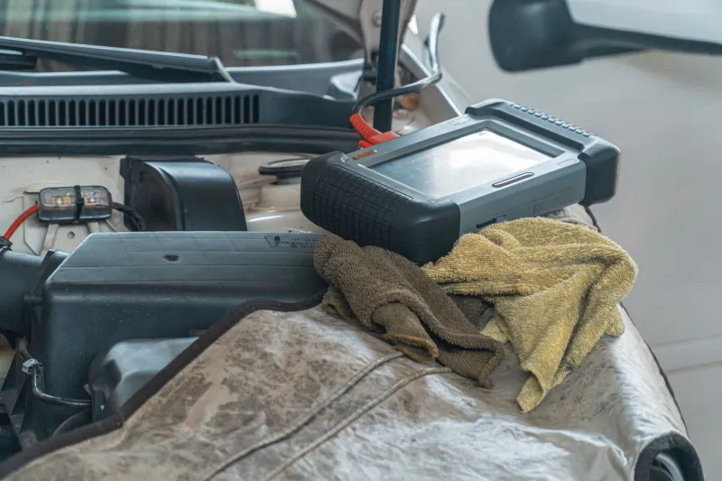
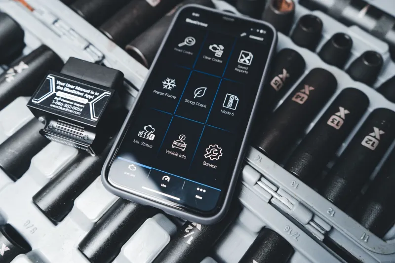
If you have a mid-range scan tool or a Bluetooth OBD-II adapter with a live data app, you can watch the sensor's output in real time — and that tells you a lot.
A failing sensor often shows erratic, random-looking values that jump around with no relationship to actual engine conditions. A wiring problem tends to produce a different pattern: the reading either flatlines at an extreme value (like -40°F or 266°F on a temp sensor), or it cuts in and out suddenly rather than drifting.
Also pay attention to whether the reading changes when you tap or wiggle the connector. If tapping the harness causes the live data value to jump, you've got a mechanical connection issue — not a sensor that needs replacing.
Compare the suspect sensor's reading to related parameters too. If your coolant temp sensor is reading 40°F on a warm engine but your intake air temp sensor shows 85°F, something doesn't add up. Cross-referencing live data streams is one of the fastest ways to catch a sensor that's feeding the ECU impossible data.
Questions to Ask Before You Approve a Repair
If you're taking the car to a shop rather than diagnosing it yourself, you have every right to ask a few pointed questions:
- Did you test the reference voltage and ground circuit at the sensor connector?
- What did the live data show before the sensor was replaced?
- Was the wiring harness and connector inspected for damage or corrosion?
A shop that did the circuit testing will have answers. A shop that went straight to the part might get defensive. Neither response is definitive, but it tells you how thorough the diagnostic process actually was.
Also worth asking: Is this a common failure pattern for this vehicle? On some platforms — certain GM trucks, older Fords, high-mileage Jeeps — wiring harness issues near the firewall or exhaust are well-documented. A mechanic familiar with your vehicle's history will know to look there first.
Real-World Example: When the Wiring Was the Real Story
Take a 2008 Silverado with a P0138 — O2 sensor high voltage on bank 1, sensor 2. Classic code, right? New O2 sensor goes in. Code comes back in three days. Second shop replaces the sensor again with an OEM part. Still comes back.
Third look: a technician traces the wiring and finds a section of the O2 sensor harness that had been rubbing against a heat shield. The insulation had worn through and the bare wire was intermittently grounding out against the shield, sending a falsely high voltage reading to the ECU. The sensor was never the problem. A short length of heat-resistant wire loom and a proper repair of the damaged section fixed it for good — total parts cost under $10.
That's not a rare story. It's a common one.
The Bottom Line
OBD-II codes are a starting point, not a parts list. When a code flags a sensor, the honest diagnostic process requires verifying that the sensor's circuit is actually delivering clean power, a solid ground, and an accurate signal path — before any parts get swapped. Skipping that step is how you end up buying three sensors for a problem that a $6 piece of wire loom would have solved.
Next time a sensor code comes up, slow down. Grab a multimeter, check the connector, watch the live data. The answer might not be in the part. It might be in the wire that's supposed to be keeping that part honest.